
Whats up guys, back again with another tutorial for installing the Viper Dual Nand V2 into a Corona console.
DISCLAIMER — The photo of the Corona Motherboard that I use is a 4GB model (I couldnt get any good pics of my 16mb board). At the time of writing this, the viper v2 is not supported on 4GB models until Element form TheModShop releases a 4GB adapter for the Viper V2. It is possible to wire the chip in, however I cannot advise on flashing your 4GB nand to the chip.
Now there are 3 consoles you can use the Viper V2 with as of now:
Trinity – 2 install methods, no adapter required.
Corona – 1 install method (2 if you use coolrunner with muffin install), adapter required.
Phats (Jasper, Falcon etc.) – 1 Install method (unless you use 5v based glitch chip for phat), adapter required.
So the original Viper was made for the trinity, it was a moderately difficult to install because of having to solder to many small points on your glitch chip (mainly ace v3) thankfully element revised this version and released the V2. The V2 is great because you dont have to solder to resistors on your glitch chip now. The only part people may find difficult is soldering in your nand indicator LED, which will be covered.
Things you will need:
- Viper Dual Nand V2
- Corona Adapter
- JRP or NAND-X
- Soldering Iron, flux etc.
- 26awg – 30awg wire (26 for positive and ground, 30 for the rest of the points)
- Skills and patience
So to start off, you want to strip your console down to the bare motherboard, and flip it over to the bottom side.Take your Corona adapter and set it on like so:
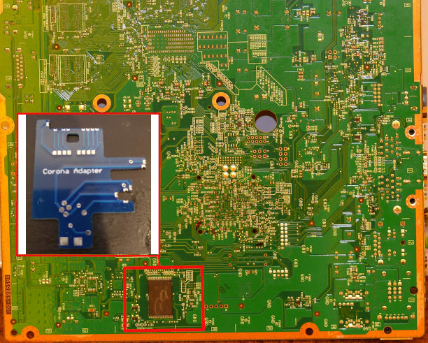
Ignore the NAND chip on bottom side as this is a photo of a 4GB Model
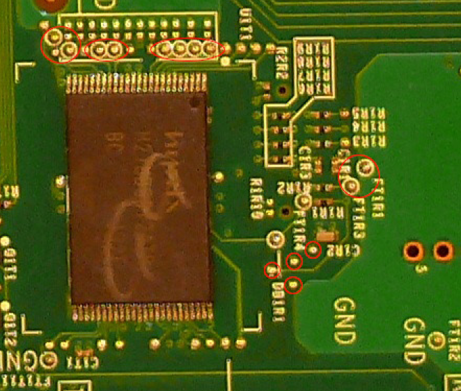
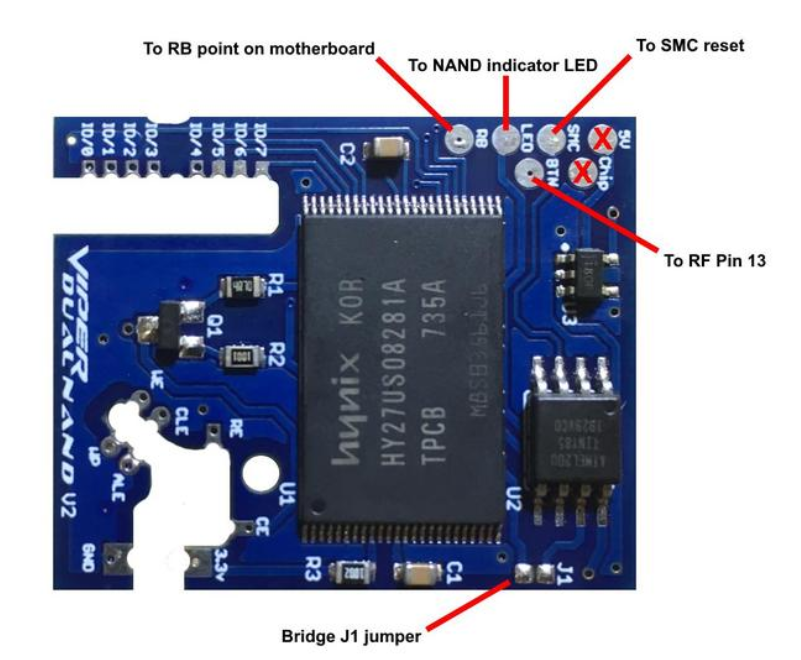
Adapter Points
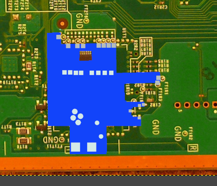
Adapter Position
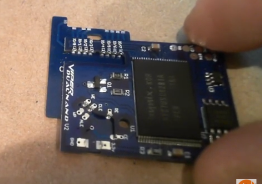
Tape or even hot glue it down to anchor it, so you can solder in the nand points, and the ground near the bottom of the adapter.Once you got that down and anchored, set the Viper Dual Nand V2 on the adapter like so.
Once All your points are soldered, and you are happy with how it is, always be sure to double check your points. You dont want to get it all back together to realize one of your points isnt good.
Next up is getting the correct points on the actual motherboard connected to the Viper V2.
^^^ Do note that this is for the “Type A” installation… The Type A requires you to have a 5V based glitch chip (such as ACE V3) and have 15432 timing files as they can recognize the retail nand and wont glitch when you have the retail nand selected.
NOTE — I personally have had it work without 15432 timing, but it is strongly recommended to use 15432 timing as regular timing has not been extensively tested yet. I will include “Type B” for the folks who have a 3v3 based chip (like Coolrunner with muffin install) as you wire your Chips VCC (3v3) to the Viper and the Viper takes care of disabling your chip while your retail nand is selected.
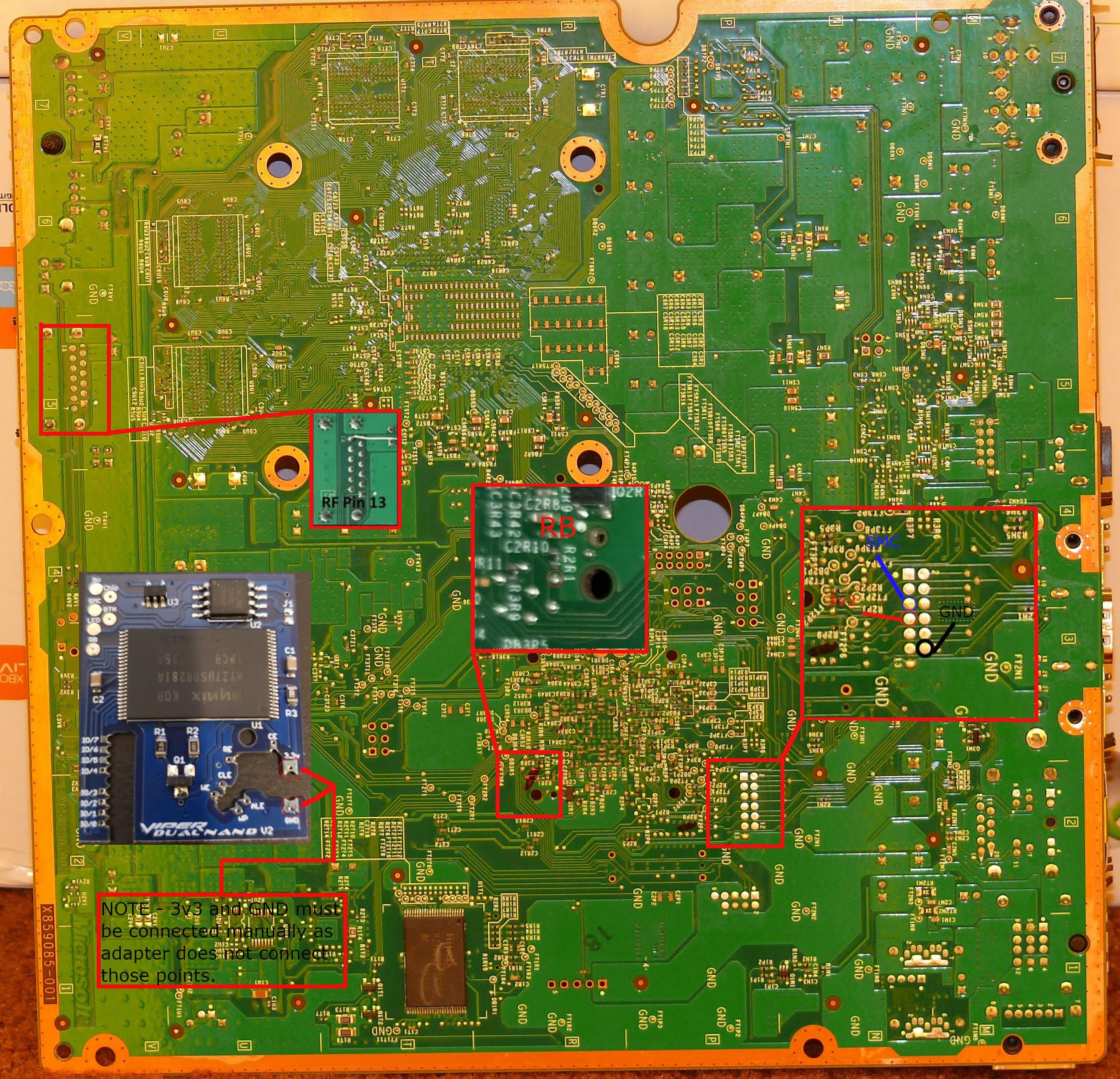
^^^ “Type A” Install ^^^
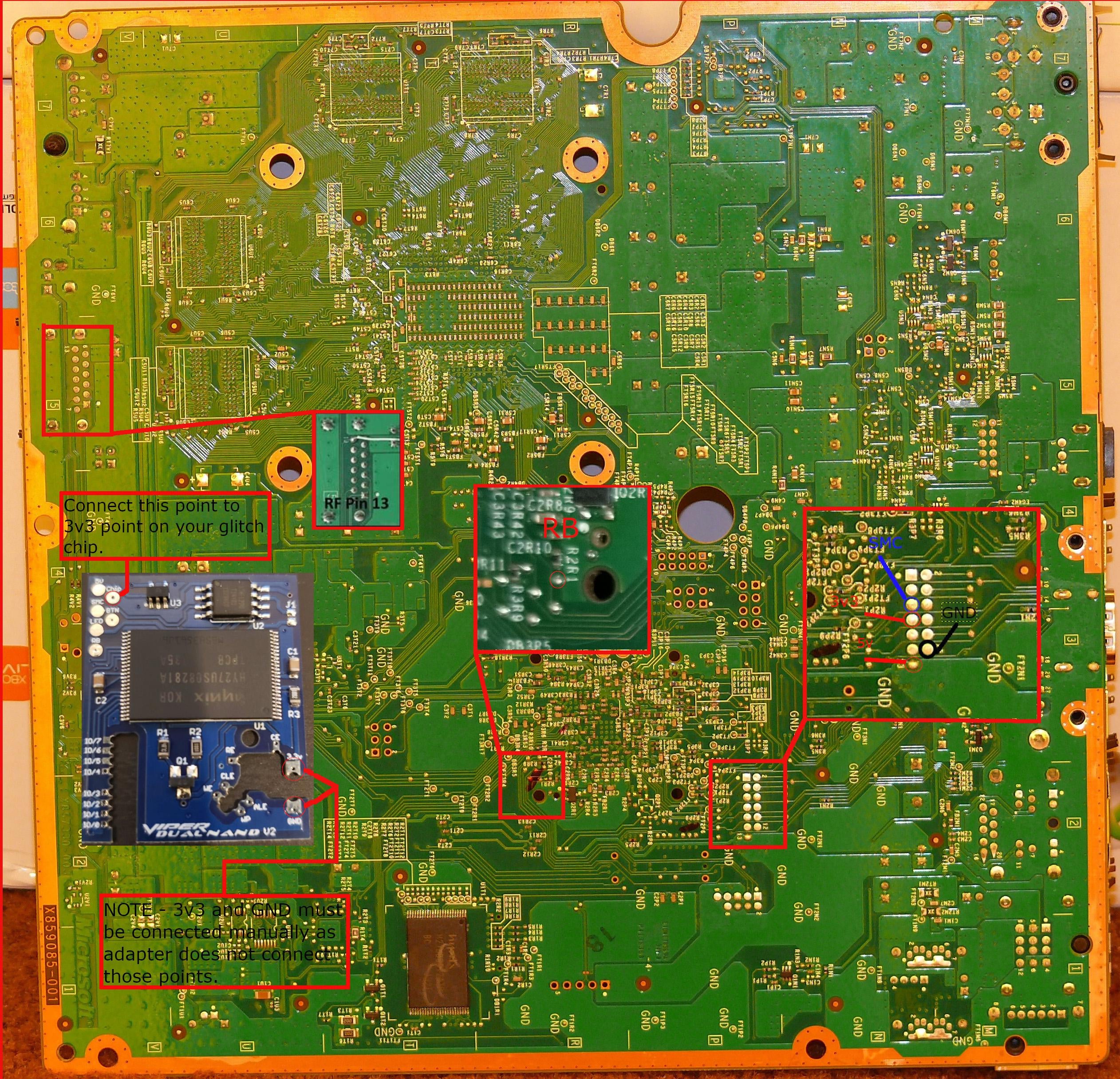
^^^ “Type B” Install ^^^
Once you have all of those points soldered in for whichever install method you choose, the only thing left is your Nand indicator light. BE VERY CAREFUL as the Nand indicator light involves scraping away at the solder mask to essentially create a negative point for you to solder your light to. It is recommended that you get a fiberglass pen to scrape away at the solder mask. However most people might be using a blade of some sort, which is fine but be careful.
On the Slim ROL boards (Ring OF Light), the points differ from the phat consoles ROL boards. It will be easier for you to scrape away at one of the side lights rather than in the middle light (as I recommend the middle light on the phats). Just choose whichever led you want and VERY CAREFULLY scrape away at the solder mask until you have a decent point to solder your LED to.
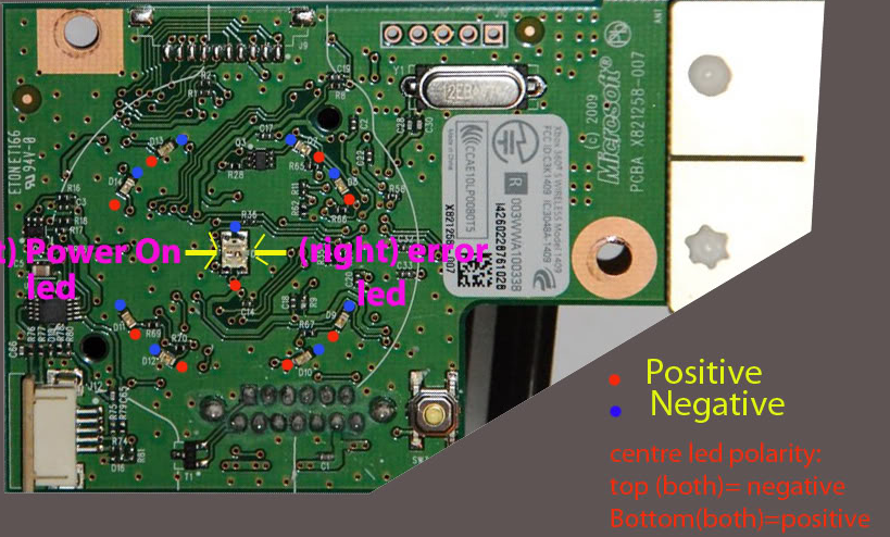
Once you have your point scraped, apply flux, tin and solder the negative end of your LED onto that point CAREFULLY.
Once your light is soldered into your point, be careful as is might be a fragile solder joint (which is to be expected). but now you can EITHER solder your wire onto the other side of the LED and wire it into the “LED” point on your Viper V2 (can be difficult as wire will always be attached to your ROL board)
Or you can follow this alternative (Thanks to Octal450 for bringing this to my attention as I was just running a wire from the ROL straight to the LED point on the Viper)
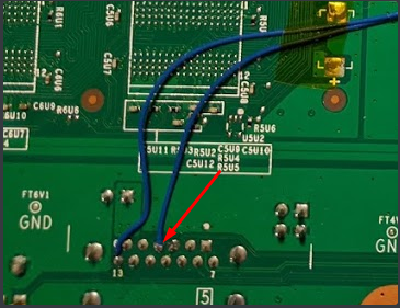
Go back to the bottom of the Motherboard and look for the RF pins (we soldered to pin 13 earlier), now you can solder your wire from the LED point on the Viper to pin 4 – as shown
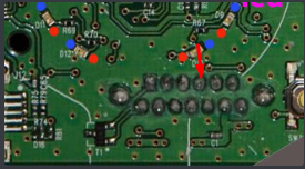
Once soldered in, you can now focus on your ROL Board. Follow the usual steps to solder the Negative point of your LED to the area that you scraped, then your going to solder a wire to the positive point on your LED. Now you can solder the other end of your LED wire, to the pin that is shown below.
Now your done. Plug the console in (do not turn it on yet) and hold in the sync button. If everything worked out and your soldering is good, then you should see your nand indicator LED flash either once or twice to indicate which nand it is on.
You can now solder your Nand wires in, hold the sync button until you switch the the Viper V2 Nand and write your Hacked image to the Vipers Nand. Then switch back to your consoles Nand and write your retail image to it.
Boom your done, now with the way its set up, if you want to revert your console back to retail, all you have to do is remove all chips.
Big thanks to TheModShop for providing is with the Viper, Viper V2, and the adapters. Thanks to Octal450 for pointing out the RF passthrough